Saturday, December 26, 2009

JunOS - Recover BGP password


JunOS - Recover BGP password


When you need to recover missing BGP MD5 password on Juniper routers, you have the possibility to extract it from a specific file.
First, you have to start a shell:
alex@M10> start shell
% su -
Password:
root@M10%
After changing to the root user, you have the necessary permissions to view the file /var/etc/keyadmin.conf
root@M10% cd /var/etc/
root@M10% more keyadmin.conf
     tcp 179 0.0.0.0 <IP address> md5 instance default 0x424157395877553351436a5263586b37
tcp 179 0.0.0.0 <IP address> md5 instance default 0x393831633666333463366663
Now you can convert the HEX keys back to MD5 with this small Perl one-liner:
perl -e 'print "Hex: ";$_=<>;print "MD5: ";s/(\w\w)/\1:/g;for (split(/:/)) {printf "%s", chr(hex($_))};print "\n"'
Hex: 0x424157395877553351436a5263586b37
MD5: BAW9XwU3QCjRcXk7


Cisco Resilient Ethernet Protocol


Configuring Resilient Ethernet Protocol


Resilient Ethernet Protocol (REP) is a Cisco propietary protocol which allows you to build redundant Ethernet rings. It’s an alternative to Spanning-Tree protocol and also avoids bridging loops or responds to link failures.

Compared to STP, it offers a faster convergence time (< 300ms) and gives you a simple VLAN load-balancing method.
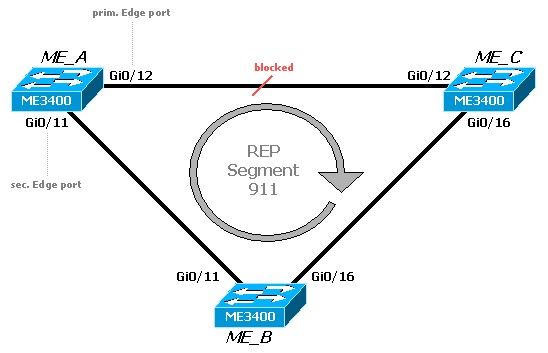
In our example, we interconnect three switches (Cisco ME3400 with me340x-metroaccess-mz.122-50.SE1.bin) to a ring topology. In REP terminology, this is called a segment.
A REP segment is a chain of ports connected to each other and configured with a segment ID. Each segment consists of standard (nonedge) segment ports and two user-configured edge ports. A switch can have only two ports belonging to the same segment, and each segment port can have only one external neighbor.configuring-rep
REP segments have the following characteristics:
  • When all ports in a segment are operational, one port (referred to as the alternate port) is in the blocked state for each VLAN.
  • If VLAN load balancing is configured, two ports in the segment control the blocked state of VLANs.
  • If one or more ports in a segment is not operational, causing a link failure, all ports forward traffic on all VLANs to ensure connectivity.
  • In case of a link failure, the alternate ports are unblocked as quickly as possible. When the failed link comes back up, a logically blocked port per VLAN is selected with minimal disruption to the network.
Valid port states in REP segments are Failed, Open, or Alternate.
  • A port configured as a regular segment port starts as a failed port.
  • After the neighbor adjacencies are determined, the port changes to alternate port state, blocking all VLANs on the interface. Blocked port negotiations occur and when the segment settles, one blocked port remains in the alternate role, and all other ports become open ports.
  • When a failure occurs in a link, all ports move to the open state. When the alternate port receives the failure notification, it changes to the open state, forwarding all VLANs.

Simple Configuration without VLAN load-balancing

First, we configure all ring interfaces as REP ports with segment ID 911. All interface have to be Layer 2 trunk interfaces.  To get REP working, we have to configure at least on edge port. For VLAN load-balancing, two edge ports are necessary.
I decided to configure the two edge ports on switch ME_A. Ports on ME_B and ME_C are configured as standard segment ports.
ME_A:
interface GigabitEthernet0/11
 description Trunk to ME_B
 port-type nni
 switchport mode trunk
 rep segment 911 edge primary

interface GigabitEthernet0/12
 description Trunk to ME_C
 port-type nni
 switchport mode trunk
 rep segment 911 edge

ME_B:
interface GigabitEthernet0/11
 description Trunk to ME_A
 port-type nni
 switchport mode trunk
 rep segment 911

interface GigabitEthernet0/16
 description Trunk to ME_C
 port-type nni
 switchport mode trunk
 rep segment 911

ME_C:
interface GigabitEthernet0/12
 description Trunk to ME_A
 port-type nni
 switchport mode trunk
 rep segment 911

interface GigabitEthernet0/16
 description Trunk to ME_B
 port-type nni
 switchport mode trunk
 rep segment 911
Activating REP produces a log message and you can examine the topology with “show rep topology” on switch ME_C:
ME_C#sh rep topology
REP Segment 911
BridgeName       PortName   Edge Role
---------------- ---------- ---- ----
ME_A             Gi0/11     Pri  Open
ME_B             Gi0/11          Open
ME_B             Gi0/16          Open
ME_C             Gi0/16          Open
ME_C             Gi0/12          Open
ME_A             Gi0/12     Sec  Alt
As you can see, port Gi0/12 on ME_A is in “Alt-state” and doesn’t forward traffic.  (VLAN load-balancing is disabled per default).
You can also examine the REP status of a particular interface with “show int <interface> rep [detail]“
ME_C#sh int g0/12 rep
Interface              Seg-id Type            LinkOp      Role
---------------------- ------ --------------- ----------- ----
GigabitEthernet0/12    911                    TWO_WAY     Open

ME_C#sh int g0/12 rep det
GigabitEthernet0/12   REP enabled
Segment-id: 911 (Segment)
PortID: 000C0024F7C1FE00
Preferred flag: No
Operational Link Status: TWO_WAY
Current Key: 00100024F7C1FE0070BB
Port Role: Open
Blocked VLAN: <empty>
Admin-vlan: 1
Preempt Delay Timer: disabled
LSL Ageout Timer: 5000 ms
Configured Load-balancing Block Port: none
Configured Load-balancing Block VLAN: none
STCN Propagate to: none
LSL PDU rx: 11400, tx: 7422
HFL PDU rx: 0, tx: 0
BPA TLV rx: 8680, tx: 860
BPA (STCN, LSL) TLV rx: 0, tx: 0
BPA (STCN, HFL) TLV rx: 0, tx: 0
EPA-ELECTION TLV rx: 148, tx: 19
EPA-COMMAND TLV rx: 0, tx: 0
EPA-INFO TLV rx: 2197, tx: 2202
I case of a link failure on Gi0/16 between ME_B and ME_C , you will see the following syslog message:
*Mar  1 07:03:17.617: %REP-4-LINKSTATUS: GigabitEthernet0/16 (segment 911) is non-operational due to
 port become non-trunk
REP converges immediately and unblocks the “Alt”-Link. Gi0/16 changes to “fail -state
ME_C#sh rep topology
REP Segment 911
Warning: REP detects a segment failure, topology may be incomplete

BridgeName       PortName   Edge Role
---------------- ---------- ---- ----
ME_C             Gi0/16          Fail
ME_C             Gi0/12          Open
ME_A             Gi0/12     Sec  Open
(All informations taken from Cisco Website)
Cisco Rep
source:http://www.net-gyver.com


Friday, December 25, 2009

Check Point NG backup, recovery, and upgrade procedures

Note: The presented bellow backup and recovery procedures will work only if both Management
Servers are on the same OS. All presented bellow actions are on the Management Server only
(SmartCenter Server).
BACKUP


1. Backup the following files:

$FWDIR/conf/Objects_5_0.C

$FWDIR/conf/rulebases_5_0.fws

$FWDIR/conf/fgrulebases_5_0.fws (if FloodGate-1 is used)

$FWDIR/conf/slprulebases_5_0.fws

$FWDIR/conf/fwauth.NDB
Note: On Windows machines fwauth.NDB file is only the pointer to the real user database file, for

example, fwauth.NDB145. In this case take the real database file -fwauth.NDB145, and rename it to

fwauth.NDB.

2. The ICA and SIC related files that should be copied are:

$FWDIR/conf/InternalCA.*

$FWDIR/conf/ICA*.*

$CPDIR/conf/sic_cert.p12

3. In addition to the above files, you also need to backup and import the following:

(Unix)

/opt/CPshared/registry/HKLM_registry.data

Note: Copy everything under 'SIC'.

(Windows)

HKEY_LOCAL_MACHINE\SOFTWARE\CheckPoint\SIC

Note: Export this key and then import it on the target machine.

4. From NG FP2, you should also copy all the files from:

$FWDIR/conf/crls


RECOVERY

1. Install new FireWall-1 NG Management Server.

2. Stop the FireWall-1 NG Management Server (cpstop).

3. Copy the backup files to the $FWDIR/conf $CPDIR/conf directories respectively, and

registry files as presented above.

4. Start the FireWall-1 management machine.(cpstart).


TROUBLESHOOTING

Manual policy file compilation

(Unix),

fwm –g .W

(Windows)

fw m –g .W


Internal Certificate Authority database reset

1. fw sic_reset

Note: 'fwm sic_reset' format on FP2 and above. If Firewall object has IKE certificates defined it is

necessary to delete them (using Policy Editor or manually in object_5_0.C).

2. Re-initialize the Internal Certificate Authority (use cpconfig
CA).

3. Restart Check Point Services (cpstart).


Restoration of a corrupted rulebases file

1. Run 'cpstop'.

2. Backup $FWDIR/conf/object_5_0.C

3. Run $FWDIR/bin/fw cpmi_upgrade (it will create a new rulebases_5_0.fws based on the

rulebases.fws)

4. Copy object_5_0.C from to backup to $FWDIR/conf.

5. Run 'cpstart'.


TIPs for MIGRATING FIREWALL-1 CONFIGURATION TO DIFFERENT PLATFORM OR

SOFTWARE VERSION


Note: All presented bellow actions are on Management Server only


*network objects*

copy old objects to new configuration:

fw confmerge old_objects_5_0.C new_objects_5_0.C > objects_5_0.C

where:

- old_objects_5_0.C - objects from old system

- new_objects_5_0.C - objects from new installed system

- objects_5_0.C - target objects database ($FWDIR/conf/objects_5_0.C)


*users*

in old system export user database to a file

fwm dbexport -f filename.txt

in new system recreate users groups manually

in new system import user database to a file

fwm dbimport -r -m -f filename.txt


*security policy*

copy rulebases.fws file or *.W files


Note:

If rules are not seen in GUI compile *.W policy files as presented above. It is also reasonable

to recreate rules manually in Policy Editor.

*diagnose*

fw checkobj


NG UPGRADE PROCEDURE FROM 4.1 VERSION

1. Run the Upgrade Verifier Utility (pre upgrade verifier). It can be downloaded from Check

Point Web site.

2. On a new machine install VPN-1/FW-1 (e.g. FP1, FP2, FP3).

3. From Check Point Web site download upgrade.4.3.tgz file, unzip it on new Firewall

machine. Then verify if the required FPx directory was created (e.g. upgrade/FP3). If not

manually create the directory (e.g. upgrade/FP3).

4. Place the following 4.1 files under upgrade/4.1

a. objects.C

b. fwauth.NDB

Note:

On Windows machines this file is only the pointer to the real database file, e.g. fwauth.NDB144. In this case take

the real database file (fwauth.NDB144), rename it to fwauth.NDB and put it in the \upgrade\4.1 directory.

c. rulebases.fws

d. fgrulebases.fws (if FloodGate-1 is installed)

5. Stop the FireWall-1 (cpstop)

6. Go to the /upgrade directory and run:

(Windows)

upgrade.bat \upgrade FP3 4.1 (upgrade from 4.1 to FP3)

(Unix)

upgrade.csh /upgrade FP3 4.1 (upgrade from 4.1 to FP3)

7. Start the FireWall (cpstart).

8. Run the Upgrade Verifier Utility (post upgrade verifier). It can be downloaded from Check

Point Web site.

Additional notes:

1. The upgrade script will backup any modified file into /upgrade/backup/ directory.

2. If you are moving from a Windows machine to Unix do dos2unix (UNIX command) on objects.C and

rulebases.fws

3. In order to keep other configuration files (e.g. gui-clients, masters) copy from 4.1 system

$FWDIR/conf directory to NG system $FWDIR/conf the following files:

- xlate.conf,

- aftpd.conf,

- smtp.conf,

- sync.conf,

- masters,

- clients,

- fwmusers,

- gui-clients,

- slapd.conf,

- serverkeys,

- product.conf.
MEF OVERVIEW

The MEF, as the defining body for Carrier Ethernet is a global industry alliance comprising more than 150 organizations including telecommunications service providers, cable MSOs, network equipment/software manufacturers, semiconductors vendors and testing organizations. The MEF’s mission is to accelerate the worldwide adoption of Carrier-class Ethernet networks and services. The MEF develops Carrier Ethernet technical specifications and implementation agreements to promote interoperability and deployment of Carrier Ethernet worldwide


Securing IOS local authentication logins

By default, the local authentication provided by IOS is fairly simple. However, there are a number of enhancements which can be enabled to greatly improve its resiliency against dictionary and brute-force login attacks.

A derivation of the login command can be used to enforce a temporary block, or "quiet period," against login attempts after a specified number of failed attempts have been made within a given time frame. For example, a router can be configured to disable inbound terminal connections for five minutes (300 seconds) after encountering five failed login attempts within 60 seconds:

Router(config)# login block-for 300 attempts 5 within 60

Issuing this command creates an access list named sl_def_acl as we'll see shortly. We can observe what happens when five failed login attempts are made within 60 seconds:

Host# telnet 10.0.0.1
Trying 10.0.0.1 ... Open
User Access Verification
Username: attempt1
Password:
% Authentication failed
Username: attempt2
Password:
% Authentication failed
Username: attempt3
Password:
% Authentication failed
[Connection to 10.0.0.1 closed by foreign host]
Host# telnet 10.0.0.1Trying 10.0.0.1 ... Open
User Access Verification
Username: attempt4
Password:
% Authentication failed
Username: attempt5
Password:
% Authentication failed
[Connection to 10.0.0.1 closed by foreign host]
Host# telnet 10.0.0.1Trying 10.0.0.1 ... % Connection refused by remote host

Notice that we never received a sixth authentication prompt. On the router, we see that this log message was generated as soon as the fifth login attempt failed:

%SEC_LOGIN-1-QUIET_MODE_ON: Still timeleft for watching failures is 33 secs, [user: ] [Source: 10.0.0.2] [localport: 23] [Reason: Login Authentication Failed] [ACL: sl_def_acl] at 15:39:25 UTC Sun Jul 26 2009

The router automatically activated the ACL sl_def_acl to deny all inbound terminal and HTTP connections for the duration of the quiet period. This ACL does not appear in the running configuration, but is visible using show ip access-lists:

Router# show ip access-listsExtended IP access list sl_def_acl 10 deny tcp any any eq telnet log 20 deny tcp any any eq www log 30 deny tcp any any eq 22 log 40 permit tcp any any eq 22 log

Our last connection attempt above triggers a match and subsequent deny on the ACL as you would expect:

%SEC-6-IPACCESSLOGP: list sl_def_acl denied tcp 10.0.0.2(16167) -> 0.0.0.0(23), 1 packet

After the quiet period has expired, a log message appears letting us know that the router is ready to accept connections again (this message appears exactly 300 seconds after the QUIET_MODE_ON alert):

%SEC_LOGIN-5-QUIET_MODE_OFF: Quiet Mode is OFF, because block period timed out at 15:44:25 UTC Sun Jul 26 2009

Of course, disabling all connection attempts during the quiet period likely does more harm than good, as legitimate administrators are affected as well. Alternatively, a custom quiet period ACL can be supplied to exempt certain source addresses.

Router(config)# login quiet-mode access-class TRUSTED_HOSTS

It's worth mentioning that, if you've properly secured remote terminal access to begin with, this command should be unnecessary.

Other login options include:

  • delay - Configure a delay between 1 and 10 seconds to wait between login attempts.
  • on-failure - Log individual login failures.
  • on-success - Log individual successful logins.


source:packetlife.net

Tuesday, December 22, 2009

Storm control


Storm control


Cisco Catalyst switches provide a feature termed "storm control," which allows an administrator to suppress excessive inbound unicast, multicast, or broadcast traffic on layer two interfaces. This can be handy to protect against broadcast storms resulting from spanning tree misconfiguration, or even unicast storms created by malfunction host NICs.

On each interface, a maximum threshold can be configured in bits or packets per second, or as a percentage of the interface bandwidth. If incoming traffic of the specified type exceeds its threshold during a polling interval (one second), traffic is blocked until the incoming rate drops below the configured falling interval. Consider the following traffic graph:


In interval T0, inbound traffic is accepted as its rate never exceeds the rising threshold. In T1, the rising threshold is exceeded, and the switch makes a note to block incoming traffic for the next interval. In T2, traffic is blocked, but the switch continues to monitor the incoming rate. Although the rate has fallen below the rising threshold, it still exceeds the falling threshold, so the switch will continue to block traffic for the next interval.

During T3, traffic stays below the falling interval, so the switch removes the blocking for T4. Although traffic in T4 exceeds the falling threshold again, traffic will not be blocked for the next interval as the rising threshold hasn't been exceeded.

Configuring storm control on an interface is simple. At a minimum you'll need to specify a traffic type (unicast, multicast, or broadcast) and a rising threshold:


Switch(config-if)# storm-control broadcast level bps 1m 500k


In the above example, we have configured storm control for broadcast traffic with a 1 Mbps rising threshold and a 500 Kbps falling threshold. Note that specifying a falling threshold is optional; if omitted, the falling threshold will default to the value of the rising threshold (effectively removing it).


show storm-control displays interfaces configured with storm control and the state of each:


Switch# show storm-control

Interface Filter State Upper Lower Current

--------- ------------- ----------- ----------- ----------

Fa0/5 Forwarding 1m bps 500k bps 0 bps

Observe how the output changes when the upper (rising) threshold for broadcast traffic is exceeded:


Switch# show storm-control

Interface Filter State Upper Lower Current


--------- ------------- ----------- ----------- ----------


Fa0/5 Blocking 1m bps 500k bps 2.08m bps

Additionally, the switch will generate a log message notifying administrators of the detected storm:


%STORM_CONTROL-3-FILTERED: A Broadcast storm detected on Fa0/5. A packet filter action


has been applied on the interface.


When the incoming rate drops below the lower (falling) threshold, the interface filter returns to forwarding:


Switch# show storm-control


Interface Filter State Upper Lower Current


--------- ------------- ----------- ----------- ----------


Fa0/5 Forwarding 1m bps 500k bps 48.81k bps


Lastly, the storm-control action trap command can be used under interface configuration to send SNMP traps in the event of a storm rather than the default behavior of blocking incoming traffic.


Friday, December 18, 2009

Embedded Event Manager


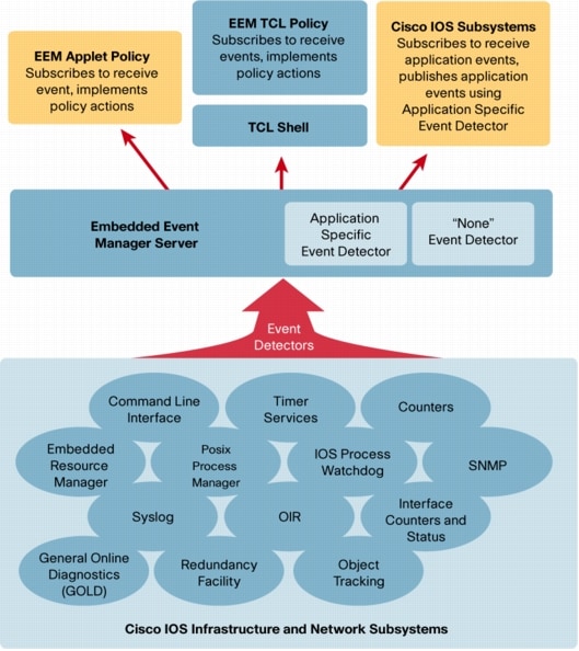
EEM is a powerful and flexible tool to automate tasks and customize the behavior of Cisco IOS and the operation of the device. Customers can use EEM to create and run programs or scripts directly on a router or switch. The scripts are referred to as EEM Policies and can be programmed using a simple CLI-based interface or using a scripting language called Tool Command Language (TCL). EEM allows customers to harness the significant intelligence within Cisco IOS Software to respond to real-time events, automate tasks, create customer commands and take local automated action based on conditions detected by the Cisco IOS Software itself


Example:
> period 600
> action 100 cli command "enable"
> action 110 cli command "configure terminal"
> action 120 cli command "router bgp 666"
> action 130 cli command "neighbor 172.16.10.3 shutdown"
> action 140 syslog msg "Neighbor 172.16.10.3 shutdown by EEM"
> action 150 publish-event sub-system 798 type 100 arg1 "shutdown"
> event manager applet BGPADJ_NOSHUT
> event timer countdown time 120
> action 100 cli command "enable"
> action 110 cli command "configure terminal"
> action 120 cli command "router bgp 666"
> action 130 cli command "no neighbor 172.16.10.3 shutdown"
> action 140 syslog msg "Neighbor 172.16.10.3 noshut by EEM

Proxy ARP

This is an example of how proxy ARP works:


5_01.gif


The Host A (172.16.10.100) on Subnet A needs to send packets to Host D
(172.16.20.200) on Subnet B. As shown in the diagram, Host A has a /16 subnet
mask. What this means is that Host A believes that it is directly connected to
all of network 172.16.0.0. When Host A needs to communicate with any devices it
believes are directly connected, it sends an ARP request to the destination.
Therefore, when Host A needs to send a packet to Host D, Host A believes that
Host D is directly connected, so it sends an ARP request to Host D.

In order to reach Host D (172.16.20.200), Host A needs the MAC address
of Host D.

Therefore, Host A broadcasts an ARP request on Subnet A, as shown:


Sender's MAC Address


Sender's IP Address


Target MAC Address


Target IP Address


00-00-0c-94-36-aa


172.16.10.100


00-00-00-00-00-00


172.16.20.200


In this ARP request, Host A (172.16.10.100) requests that Host D
(172.16.20.200) send its MAC address. The ARP request packet is then
encapsulated in an Ethernet frame with the MAC address of Host A as the source
address and a broadcast (FFFF.FFFF.FFFF) as the destination address. Since the
ARP request is a broadcast, it reaches all the nodes in the Subnet A, which
includes the e0 interface of the router, but does not reach Host D. The
broadcast does not reach Host D because routers, by default, do not forward
broadcasts.


Since the router knows that the target address (172.16.20.200) is on
another subnet and can reach Host D, it replies with its own MAC address to
Host A.


Sender's MAC Address


Sender's IP Address


Target MAC Address


Target IP Address


00-00-0c-94-36-ab


172.16.20.200


00-00-0c-94-36-aa


172.16.10.100


This is the Proxy ARP reply that the router sends to Host A. The proxy
ARP reply packet is encapsulated in an Ethernet frame with MAC address of the
router as the source address and the MAC address of Host A as the destination
address. The ARP replies are always unicast to the original requester.


Upon receipt of this ARP reply, Host A updates its ARP table, as shown:


IP Address


MAC Address


172.16.20.200


00-00-0c-94-36-ab


From now on, Host A forwards all the packets that it wants to reach
172.16.20.200 (Host D) to the MAC address 00-00-0c-94-36-ab (router). Since the
router knows how to reach Host D, the router forwards the packet to Host D. The
ARP cache on the hosts in Subnet A is populated with the MAC address of the
router for all the hosts on Subnet B. Hence, all packets destined to Subnet B
are sent to the router. The router forwards those packets to the hosts in
Subnet B.


The ARP cache of Host A is shown in this table:


IP Address


MAC Address


172.16.20.200


00-00-0c-94-36-ab


172.16.20.100


00-00-0c-94-36-ab


172.16.10.99


00-00-0c-94-36-ab


172.16.10.200


00-00-0c-94-36-bb


Note: Multiple IP addresses are mapped to a single MAC address, the MAC
address of this router, which indicates that proxy ARP is in use.


The interface of the Cisco must be configured to accept and respond to
proxy ARP. This is enabled by default. The no ip
proxy-arp
command must be configured on the interface of the
router connected to the ISP router. Proxy ARP can be disabled on each interface
individually with the interface configuration command no ip
proxy-arp
, as shown:


Router# configure terminal
Enter configuration commands, one per line. End with CNTL/Z.
Router(config)# interface ethernet 0
Router(config-if)# no ip proxy-arp
Router(config-if)# ^Z
Router#


In order to enable proxy ARP on an interface, issue the ip
proxy-arp
interface configuration command.


Note: When Host B (172.16.10.200/24) on Subnet A tries to send packets to
destination Host D (172.16.20.200) on Subnet B, it looks into its IP routing
table and routes the packet accordingly. Host B (172.16.10.200/24) does not ARP
for Host D IP address 172.16.20.200 because it belongs to a different subnet
than what is configured on Host B ethernet interface 172.16.20.200/24.


Advantages of Proxy ARP


The main advantage of proxy ARP is that it can be added to a single
router on a network and does not disturb the routing tables of the other
routers on the network.

Proxy ARP must be used on the network where IP hosts are not configured
with a default gateway or do not have any routing intelligence.


Disadvantages of Proxy ARP

Hosts have no idea of the physical details of their network and assume
it to be a flat network in which they can reach any destination simply by
sending an ARP request. But using ARP for everything has disadvantages. These
are some of the disadvantages:
  • It increases the amount of ARP traffic on your segment.

  • Hosts need larger ARP tables in order to handle IP-to-MAC address
    mappings.

  • Security can be undermined. A machine can claim to be another in
    order to intercept packets, an act called "spoofing."


  • It does not work for networks that do not use ARP for address
    resolution.


  • It does not generalize to all network topologies. For example, more
    than one router that connects two physical networks.


.


Thursday, December 17, 2009

Protocol Overhead

Ethernet


Ethernet frame format:

6 byte dest addr

6 byte src addr

[4 byte optional 802.1q VLAN Tag]

2 byte length/type

46-1500 byte data (payload)


4 byte CRC


Ethernet overhead bytes:
12 gap + 8 preamble + 14 header + 4 trailer = 38 bytes/packet w/o 802.1q
12 gap + 8 preamble + 18 header + 4 trailer = 42 bytes/packet with 802.1q

Ethernet Payload data rates are thus:
1500/(38+1500) = 97.5293 % w/o 802.1q tags
1500/(42+1500) = 97.2763 % with 802.1q tags

TCP over Ethernet:
Assuming no header compression (e.g. not PPP)
Add 20 IPv4 header or 40 IPv6 header (no options)
Add 20 TCP header
Add 12 bytes optional TCP timestamps
Max TCP Payload data rates over ethernet are thus:
(1500-40)/(38+1500) = 94.9285 % IPv4, minimal headers
(1500-52)/(38+1500) = 94.1482 % IPv4, TCP timestamps
(1500-52)/(42+1500) = 93.9040 % 802.1q, IPv4, TCP timestamps
(1500-60)/(38+1500) = 93.6281 % IPv6, minimal headers
(1500-72)/(38+1500) = 92.8479 % IPv6, TCP timestamps
(1500-72)/(42+1500) = 92.6070 % 802.1q, IPv6, ICP timestamps

UDP over Ethernet:
Add 20 IPv4 header or 40 IPv6 header (no options)
Add 8 UDP header
Max UDP Payload data rates over ethernet are thus:
(1500-28)/(38+1500) = 95.7087 % IPv4
(1500-28)/(42+1500) = 95.4604 % 802.1q, IPv4
(1500-48)/(38+1500) = 94.4083 % IPv6
(1500-48)/(42+1500) = 94.1634 % 802.1q, IPv6


An excellent source of ethernet information is Charles Spurgeon’s Ethernet Web Site.


Notes:


  1. 48-bit (6 byte) ethernet address have a 24-bit “Organizationally Unique Identifier” (OUI) assigned by IEEE + a 24-bit number assigned by the vendor.
  2. The minimum ethernet payload (data field) is 46 bytes which makes a 64 byte ethernet packet including header and CRC.

  3. The maximum ethernet payload (data field) is 1500 bytes which makes a 1518 byte ethernet packet including header and CRC. When 802.1q added an optional 4-byte VLAN Tag Header, they extended the allowed maximum frame size to 1522 bytes (22 byte header+CRC).

  4. The bit speed of 100 Mbps ethernet on the wire/fiber is actually 125 Mbps due to 4B/5B encoding. Every four data bits gets mapped to one of 16 5-bit symbols. This leaves 16 non-data symbols. This encoding came from FDDI.

  5. The original Ethernet II spec had a two byte type field which 802.3 changed to a length field, and later a length/type field depending on use: values 1536 and over are types, under 1536 lengths.


Gigabit Ethernet with Jumbo Frames


Gigabit ethernet is exactly 10 times faster than 100 Mbps ethernet, so for standard 1500 byte frames, the numbers above all apply, multiplied by 10. Many GigE devices however allow “jumbo frames” larger than 1500 bytes. The most common figure being 9000 bytes. For 9000 byte jumbo frames, potential GigE throughput becomes (from Bill Fink, the author of nuttcp):


Theoretical maximum TCP throughput on GigE using jumbo frames:

(9000-20-20-12)/(9000+14+4+7+1+12)*1000000000/1000000 = 990.042 Mbps

MTU MTU GigE Mbps

IP Ethernet InterFrame Gap (IFG), aka
Header Header InterPacket Gap (IPG), is
a minimum of 96 bit times
TCP FCS from the last bit of the
Header FCS to the first bit of
Preamble the preamble
TCP
Options Start
(Timestamp) Frame
Delimiter
(SFD)

Inter
Frame
Gap
(IFG)

Theoretical maximum UDP throughput on GigE using jumbo frames:

(9000-20-8)/(9000+14+4+7+1+12)*1000000000/1000000 = 992.697 Mbps

Theoretical maximum TCP throughput on GigE without using jumbo frames:

(1500-20-20-12)/(1500+14+4+7+1+12)*1000000000/1000000 = 941.482 Mbps

Theoretical maximum UDP throughput on GigE without using jumbo frames:

(1500-20-8)/(1500+14+4+7+1+12)*1000000000/1000000 = 957.087 Mbps


Public route-servers

From: http://www.cymru.com/Documents/secure-bgp-template.html


route-views.oregon-ix.net

ner-routes.bbnplanet.net

route-server.cerf.net

route-server.ip.att.net

route-server.east.attcanada.com

route-server.west.attcanada.com

route-server.cbbtier3.att.net

route-server.gblx.net

route-server.as5388.net

route-server.savvis.net

route-server.colt.net

route-server.opentransit.net

route-server.gt.ca

public-route-server.is.co.za (South African routes only)

route-server.belwue.de

route-views.on.bb.telus.com

route-views.ab.bb.telus.com

route-server.ip.tiscali.net

route-server.wcg.net

route-server.manilaix.net.ph

route-server.ip.ndsoftware.net

route-server.utah.rep.net

route-server.he.net

zebra.swinog.ch


Just telnet to one of the above route-servers and you can login via guest/anonymous account. There you go and you can use some basic show commands.